|
|
|
GSHP Open Source GPM
Last Post 13 Nov 2014 08:25 AM by jonr. 158 Replies. |
Sort:
|
|
 Prev Next Prev Next |
You are not authorized to post a reply. |
|
|
|
nooboo

Basic Member

Posts:136
 |
| 25 Jun 2012 04:42 PM |
|
Another helpful comment by 'Furd' elsewhere:
"If this is a single stage centrifugal pump then throttling the output IS the correct method of decreasing the flow. Throttling the flow will decrease the power used by the pump even though the discharge pressure rises. This is because centrifugal pumps are what are classified as dynamic pumps and the power input is directly proportional to the flow. Minimum power input will be achieved with no flow through the pump and maximum power input with maximum flow through the pump.
Large centrifugal pumps are always started with the discharge valve closed to reduce the starting load on the driving motor.
Now with multi-stage pumps the procedure may be a bit different as the pump will have a certain minimal flow rate that must be maintained to keep the pump from overheating. This is usually accomplished with a small bypass pipe and valve configuration.
Read more: http://www.doityourself.com/forum/electrical-c-d-c/473501-slowing-pump-vfd-static.html#ixzz1yq6w8DRw |
|
|
|
|
nooboo
Basic Member
Posts:136
|
| 25 Jun 2012 05:39 PM |
|
Posted By jonr on 25 Jun 2012 03:52 PM
I expect that there are people out there with open loop heat pumps that discharge 40' down a borehole or hill. Without a valve, this means that the water is continually vaporizing in the heat exchanger - a really bad idea.
Avoid the issue with the valve and then a vacuum break on the discharge. Keeping pressure high and temperature low will minimize fouling.
I might be one of those with bad ideas... My Source water is highly potable, but does have Fe and Mn deposits that collect on my plumbing which has resulted in stuck valves and or leaky valves with deposits visible through the semi-opaque pex tubing. The Wirsbo dealer here, Fergy, said about one particular valve: "We have never had a leak in that type of valve." Well they do now. |
|
|
|
|
Blake Clark

New Member
Posts:55
|
| 25 Jun 2012 05:42 PM |
|
Slowing 3 phase motors with 1ph to 3ph inverters is how everyone besides Grundfos does it. Grundfos actually does it this way too - sort of. It's just that their inverter is resident to the pump housing and instead of induction 3 phase, they use permanent magnet 3 phase. Any variable speed pump will behave nearly identically to Grundfos. I'm only using the SQE series to illustrate because that's what I'm familiar with and have the data for. SQE also eeks out a little more total efficiency at low speeds over others due to better motor efficiency.
No consensus on flow through hx - it's a matter of finding the flow that maximizes the total system COP. Lower flows mean higher delta t's across the hx and higher compressor current. Higher flows mean less compressor current and higher pumping current. No magic answer - except to say that open loop systems have very good entering water temperatures compared to closed systems. The downside of open is usually high pumping energy (and fouling) You can almost always get by with lower flows with an open system. The specs I have for a 4 ton system is 9 GPM minimum at 40 degrees EWT. With an open system, you have to be concerned about freezing, of course, but even 10 GPM should give you enough wiggle room.
At 17.6 GPM with 30,000 BTU heat extraction (typical 4 ton specs) you've only got a 3.5 degree drop in water temperature across the hx. At 10 GPM, you'll see a 6 degree drop. You probably couldn't even measure the increase in compressor current with a 2.5 degree difference in leaving water temperature. You will, however, definitely consume 75 percent more pumping energy at 17.6 GPM vs 10 GPM.
One thing about reducing speed with a centrifugal pump - it's not a direct cause and effect relationship with flow rate. With a positive displacement pump, yes, with centrifugal, not exactly. The only way to really control flow with a variable speed centrifugal is still to use a throttle of some kind. At uber-low pressures, the roll of "throttle" is played by the pressure drop in the hx itself. There is enough resistance in the hx coil to meter flow if the pressures are low enough. The guy with the "bypass valve" has been banned from this site, but not entirely because his theory doesn't hold water - ha!. As I just stated, you have to throttle (in one form or another) to control the flow of a variable speed pump. Absolutely true.
However, I'm not advocating using variable speed just to reduce flow - no -no -no - no! I'm advocating using a variable speed pump to correctly match flow and head with much higher precision than can be done with a single speed - especially at fractional hp. A correctly sized pump will trounce a throttled pump for efficiency every time. The best design feature of a variable speed pump is NOT that it can vary flow at constant pressure- though that's how they try to sell them. It's that a variable speed pump can fill the role of a whole series of single speed pumps if you know how to calculate their peak efficiency curve. The other advantage is the fine tuning that can't be done with a single speed.
As to johnr's concern about boiling water - not very likely. At 28.67" hg, which is 96% of absolute vacuum and about the max you could ever pull with a drop pipe, the boiling temperature of water is 86 degrees. Easy to see that temperature in a closed loop, but not likely in a pump and dump with adequate flow. I have a small metering valve downstream of the hx that steps the pressure down to the full "pull" of my 100 foot drop pipe. If thing's were a'boilin', I'd certainly hear it going snap crackle pop through that valve. Not a peep. My hx is at 20"hg - the boiling temperature of water at 20" hg is 158 degrees.
I'm not sure how one "avoids the issue with the valve" by "keeping pressure high". Keeping pressure "high" when idle necessitates a valve of some kind. It seems to me that fresh water from a well that spends fractions of a second in a heat exchanger even under vacuum is going to have less potential for fouling than a system idle for 10 weeks at 0 psi. Pressurize when idle and I doubt you'll have any more problems with fouling than is typical with open loops. |
|
|
|
|
nooboo
Basic Member
Posts:136
|
| 25 Jun 2012 06:38 PM |
|
Posted By engineer on 03 Jun 2012 10:26 PM
may be required to provides some headroom against freezing.
Head against freezing seems like a likely GPM flow, design constraint for these cold nights.
Thanks for the info Blake! Very cool learning about these crazy pumps! And it is very easy to make mistakes if the details are not attended to. So, here I am: ready to make some source water pump decisions. Not crazy about spending another $2k on the best, and am willing to settle for 'good', depending on payback and if something my wife can run once I have my stroke figuring this out.
Pressurize when idle
How would you do that? It would need to be dynamic, rt?
I thought at first that I would use a Spring Check Valve before the HX, which would put the HX in a vacuum. That isn't right from I found.
What's next... |
|
|
|
|
nooboo
Basic Member
Posts:136
|
| 25 Jun 2012 07:49 PM |
|
Reviewing the Idronic '9' Manual, I should fully expect to have iron fouling inside the HX with the shallow well plan at this location.
Fe here is > 0.20ppm ferrous and DO is < 0.5ppm
I can either plan on yearly HYDROCHLORIC ACID TREATMENT or dig a well past the iron.
Also flow is calculated on p17 of the Idronic_9 manual. |
|
|
|
|
Blake Clark
New Member
Posts:55
|
| 25 Jun 2012 09:14 PM |
|
Not too many options for sustaining back pressure after pump shut down. One is an automated valve. The price range is staggering, everything from a $20 irrigation valve to multiple hundreds for motorized ball valves. I sprang for the $300 motorized ball valve for reliability and ability to operate over the huge range in pressures my system cycles through. I was also trying to keep flow restriction to a minimum. There are pros who install the $300 valve, and the pros who install the $20 irrigation valve and teach their customers how to change it out when it goes bad :-). With what you were saying about Fe content - oh boy - I think you're into the $300 category.
The other option is what's called a "back pressure regulating valve" or similarly a "pressure sustaining valve". These use springs and diaphragms to maintain a pre-set pressure upstream regardless of discharge pressure. Set up correctly, these can also used as your flow regulator. A quick google search will turn up several, but before you get too excited, the 1 1/4" cash acme valve runs $1,600. Smaller ones could be made to work - they start at around $350 for 1/4 inch and go up from there.
O.K., so back to valves. The most common control strategy with open systems is very similar to a domestic supply system. A pressure tank with a differential pressure switch connected to the pump leads. The geo unit opens the valve and water is drawn from the tank, pressure drops and turns the pump on. At the end of cycle, valve closes, pressure builds and pump shuts off. You would want to set up the pressure switch and tank pre-charge so that the pump doesn't cycle while the geo unit is operating. This just means setting the upper limit higher than your operating pressure, but not too high or your pump won't shut off. You don't need a huge tank, because the goal isn't to store water, just provide a buffer for start up and shut down. A few gallons is probably all you need, and a hot water expansion tank would probably work.
Since it sounds like you will probably want to mess around with different flows, I would recommend using a simple manual ball valve as your throttle. Install the ball valve (throttle) and your automated valve on the discharge side of the hx. Adjustment to flow is a simple matter of turning the handle on the ball valve.
You don't have to wed yourself to the magical 17.6 GPM or any other flow for that matter. If you want to see how your system responds to a wide open throttle - go for it. With your discharge siphon, counterintuitively maybe, wide open throttle will lead to your lowest (probably vacuum) pressures and your highest flow. As you crack down on the "throttle" back pressure will build and flow will decrease. At this point, your siphon suction is not contributing to efficiency at all. You will probably witness that your highest amp draw on the pump is at the lowest system pressure during wide open throttle. This is because you would be pumping at a very high flow. You should see the amps back off as you close the throttle valve. As you experiment, you should be able to find a sweet spot for power draw. Basically, if you find a throttle setting that minimizes your pumping power, go with that and see if the flow is adequate for the unit. If its not, you can always increase it. You don't need to have that part figured out in advance - if you already bought the pump anyway. You won't necessarily be pumping at maximum "efficiency" on the magical curve, but if you're at minimum power consumption and the flow still works for the unit - who cares?
Once you're comfortable with your ball valve flow rate, there's no reason you couldn't just weld the sucker at that spot. Or, you can purchase any number of flow regulators that will do a slightly more subtle job than your ball valve. Some are just a hole in a piece of rubber, some are dynamic and constantly adjust to maintain constant flow. A good flow regulating valve can be had at an HVAC outlet for less than $200. |
|
|
|
|
jonr

Senior Member
Posts:5341
|
| 25 Jun 2012 10:05 PM |
|
As to johnr's concern about boiling water - not very likely. At 28.67" hg, which is 96% of absolute vacuum and about the max you could ever pull with a drop pipe, the boiling temperature of water is 86 degrees. No. If it weren't for the water vaporizing (or other gases leaving the water), the pressure would go right down to ~0 psia. 29.92" hg = 33.9' of water, that's all it takes. Would you hear it - quite possibly not. |
|
|
|
|
Blake Clark
New Member
Posts:55
|
| 25 Jun 2012 10:32 PM |
|
Not true. First, it's not "water vaporizing" and "dissolved gasses" that prevent a system from reaching absolute vacuum. Though minimum pressure is limited by the vapor pressure of a substance at a given temperature, vaporization itself is not necessary to prevent things from spiraling down to absolute vacuum in a drop pipe with water moving through it. Nor is vaporization even a given, in fact it's highly unlikely under these conditions.
Let's start with environmental conditions first. The absolute lowest possible pressure that is going to exist in a drop pipe is determined by ambient well temperature. If the ambient well temperature is 53 degrees, the lowest pressures you're going to see in there is 29.52" hg. But that's with a static column of water that's had time to cool. The warm water coming down the pipe is for all intents and purposes isolated from ambient well temperatures above the water table. So the lowest pressure you'll see in a drop pipe is determined by the temperature of the water leaving the heat exchanger. Let say that's 86 degrees. The lowest pressure in the drop pipe is therefore 28.67" hg.
Under these conditions, a pipe full of water that is above ambient temperatures can't vaporize. Why? Because there's no temperature source to draw from to supply the heat of vaporization. Heat of vaporization can't come from the water itself, because that would lower the temperature and I'm pretty sure self-cooling water under constant pressure violates some law of thermodynamics. So what you've got is liquid water at saturation temperature and pressure going down the pipe.
To get back to water boiling elsewhere, such as the heat exchanger, I've established there is no water vaporizing in the drop pipe at 28.67 hg and 86 degrees. Now, to get water to move down a pipe, there has to be a pressure difference, otherwise, the water would just sit there. So, by definition, the water at the head of the pipe will be at higher pressure than the water at the lowest pressure point. It doesn't take a whole lot of pressure to move water, lets say 2 inches of head to move 7 GPM. 2 inches of head translates as an additional .14 inches of hg. If I add .14"hg pressure, what happens? The boiling point jumps up to almost 90 degrees.
So what does this mean? It means that there's really no way that the water in the hx could boil under the vacuum created by the drop pipe unless there was significant cooling of the water before it got to the drop pipe. If for some reason there was significant cooling on the way to the drop pipe, why would you need the drop pipe?
Still not convinced? Let's look at the heat exchanger side of things. First, at 7GPM, the heat exchanger has nearly 5 FEET of pressure drop across it. Assuming the pressure drop is uniform, it's only the last 3.5% of the length of the hx where boiling would even be remotely possible - and, again, not without cooling happening somewhere prior to or inside the drop pipe and a highly impractical lack of friction head. For water to boil in the hx it has to condense somewhere. Could you go out of your way to design it this way? Sure, but the simple fact is, a typical geo drop pipe as designed makes for a very lousy condenser. You'd think if the only thing power companies had to do is run a pipe downhill to condense the steam form their turbines, they might have done that. Might save some on construction costs.
After the pump shuts off, the pressure in the pipe immediately drops, then continues to fall slowly as the water in the drop pipe cools to ambient. However, if you've followed the design guidelines I've outlined, at this point your hx is basking in high pressure tucked in safely behind the control valve. |
|
|
|
|
joe.ami

Veteran Member
Posts:4377

|
| 26 Jun 2012 10:23 AM |
|
Posted By nooboo on 25 Jun 2012 07:49 PM
Reviewing the Idronic '9' Manual, I should fully expect to have iron fouling inside the HX with the shallow well plan at this location.
Fe here is > 0.20ppm ferrous and DO is < 0.5ppm
I can either plan on yearly HYDROCHLORIC ACID TREATMENT or dig a well past the iron.
Lots of things are less aggressive for cutting iron. We have high iron contents here, but only tend to see fouling down stream of pressure. Pressure keeps a lot of the mineral suspended. Most folks who have trouble here use a small diameter drain that gets fouled.....easily remedied with a larger drain. j |
|
Joe Hardin
www.amicontracting.com
We Dig Comfort!
www.doityourselfgeothermal.com
Dig Your Own Comfort! |
|
|
Blake Clark
New Member
Posts:55
|
| 26 Jun 2012 10:52 AM |
|
Do you think it could be possible that the drain is more likely to have air/oxygen present that causes accelerated precipitation, rather than just low pressures? I can imagine a surface drain potentially having that issue, and O2 would certainly be present if there was a vacuum break installed. Do you see fouling in vertical bore-hole drop pipes with below-surface discharge? Is it common practice to instal a vacuum break in those applications? Please take these questions as sincere curiosity - not as a challenge to your experience. |
|
|
|
|
jonr
Senior Member
Posts:5341
|
| 26 Jun 2012 11:06 AM |
|
Strange, you say "not true" and then go on to repeat what I said. Must be a semantics issue. We fully agree that the level of vacuum you can draw on some water depends on temp and that it's only the last portion of a heat exchanger that sees the lowest pressure. First, it's not just "water vaporizing" and "dissolved gasses" that prevent a system from reaching absolute vacuum, it's the pressure of those gasses at ambient temperature. It's hard to have these gasses produce any pressure if they don't first exist, eh? That's called vaporizing.
I'm pretty sure self-cooling water under constant pressure violates some law of thermodynamics.
I have a steaming (aka vaporizing) cup of coffee cooling off here that demonstrates otherwise. |
|
|
|
|
Blake Clark
New Member
Posts:55
|
| 26 Jun 2012 11:16 AM |
|
I just edited the post to clarify my thoughts on vapor pressure vs vaporization. I apparently wasn't making myself clear enough that vaporization is a different animal than vapor pressure. |
|
|
|
|
jonr
Senior Member
Posts:5341
|
| 26 Jun 2012 11:18 AM |
|
I'm not sure how one "avoids the issue with the valve" by "keeping pressure high". Keeping pressure "high" when idle necessitates a valve of some kind. Parse my statement (which is a little different than your quote) as "one can avoid the issue by using a valve...". Yes, I should have noticed the potential for alternative meaning in the wording. |
|
|
|
|
nooboo
Basic Member
Posts:136
|
| 27 Jun 2012 03:11 AM |
|
The input is good, thanks to Eng, B, J, JA, and an interesting post (gone at this writing but in my email) by KT -
Blake, thanks for identifying the "by-pass" .
As long as you folks see this, realize JonR has worded such in the past that others who are as you say, -just critical and more presumptuos, have dropped out of the thread, save one.
your open minded-nesses, both B, N as well as with JonR, are so well understood and appreciated.
JonR will support your expressions of in his - of catagorically understanding them.
There is more to the facets of JonR 's practicality that others have overlooked.
Mike Solar has such practicality, but does things differently of his experience and knows pumps very well.
What you have disgenerated with your aquisolutionisms is more common thread-bound cutting commentary, and the vast majority so appreciates the lack of know-it-all posturing.
Well done blake.
and J has probably seen that iron-out does wonders (DO NOT BREATH THE SWEET SMELL AT ALL (vapor in use)) with below even 2.0 ppm , if frequently, 3 x a winter, used.
2) so works a solution of 4%-5% muriatic (? titanium) -fine on CuNi (YOU CAN ALWAYS BE PITTING AWAY RAW METAL LOCATIONS IN THE HX IMMEDIATELY) Under 4% Cu, and under 12 minutes. If you see a gren tint in Cu/ CuNi, your past error mode.
3) Acetic 6%vinegar is fine for even 20+ minutes ~ 1 to 2 gpm, flushing the desuperheater HW generator at that same time.
(so many "techs" sell desuperheaters, then let the Mr. Coffee HW maker get plugged in 2-5 years, without service clean-out drains...)
Seen- 5PPM Fe -Ferric - "clings" such that pumps needed cleaned on 3.1/2 ton GT systems pump-dump-open drains, in th well and the well flow slowed to 5gpm, every year, from originally 8 gpmn well. They went closed ECL, glhe. (Blake can well-expound: probably) Neighbor with a 70-ft deeper well (depth does not necessarily mean better) has 'softner-guys-analysis' at 8.+ PPM, "slips" Ferrous (or something like that) non-clinging translucent in walls of pipes, always at 13 GPM 6+ton since 2003.
BLAKE:
USED - not a theory, a simple bronze circ GFos ups 26-116 on a 1.1/4"-H- piping/pump on the bar in say the upper left leg if the feed to the unit,, Feed left below leg,, recirc, with a (410a) Parker Freon-T'd valve at the lower rt leg discharge (but may oscillate on a vacuum leg discharge) to GT unit can reduce the overall flow requirements by nearly 20%+ ...
I have found in 33 years GT and 1600+ hands on, and comm chillers, it is the above ~ 12/hr cycling that takes out the small subs and jets, not "the hard loading", having pumps on-going since the early 80's still. GFos forrunners of like the newer BG NRF boosters and circs, have already lasted 26 years in agressive boosting and recirculation to discharging34.1/2 degree open Fe well systems on water saver setups. Particulate can errode the blades though, as we all may know, however slowly.
Hey about .2ppm iron ... !! whats the problem? Even evacuated , EASY TO KEEP UP WITH. Less time in 10 years than all this writing above! ha! ho!
Here is what I have, starting from the pump: Pump is @ 20' in 8" casing with homemade well screen, to a insulated utilidor, to house up 14', isolation valve, purge/cleanout drain, check valve, union, HX, union, solenoid valve, flow meter, purge/cleanout drain, throttling valve, through the utilidor and out to a discharge well...
The submersible is controlled by the GSHP on-board wired controller, supplying voltage when the pump is to run; no pressure tank. |
|
|
|
|
Blake Clark
New Member
Posts:55
|
| 27 Jun 2012 09:01 AM |
|
Looks pretty good. I love the word utilidor, I don't get a chance to use it often enough.
One question and a few comments. Is your isolation valve a shutoff valve, like for maintenance?
Comments: I'm not sure how effective your solenoid valve is going to be with this arrangement. (Solenoid valves would be better off described as pressure operated valves) Running the flow regulator after the valve helps.... Except... you might end up with a sequencing problem if your pump and valve are being controlled independently. Once the pump shuts off, the pressure is going to drop immediately. If the valve isn't closed yet, it's not going to. This is typically why you would see the pump being operated with a pressure switch. You could omit the pressure switch and install a bladder tank to maintain enough pressure in the system long enough for valve operation, or somehow make sure that the valve closes before the pump shuts down. I'll leave it up to you to find a clever solution to the latter - most people do it with a bladder tank and pressure switch :-) |
|
|
|
|
nooboo
Basic Member
Posts:136
|
| 27 Jun 2012 02:14 PM |
|
Here is what I have, starting from the pump: Pump is @ 20' in 8" casing with homemade well screen, to a insulated utilidor, to house up 14', isolation valve, purge/cleanout drain, check valve, union, HX, union, solenoid valve, flow meter, purge/cleanout drain, throttling valve, through the utilidor and out to a discharge well...
The submersible is controlled by the GSHP on-board wired controller, supplying voltage when the pump is to run; no pressure tank.
Posted By Blake Clark on 27 Jun 2012 09:01 AM
...Is your isolation valve a shutoff valve, like for maintenance?
Comments: I'm not sure how effective your solenoid valve is going to be with this arrangement. (Solenoid valves would be better off described as pressure operated valves)
...
Except... you might end up with a sequencing problem if your pump and valve are being controlled independently...
...
most people do it with a bladder tank and pressure switch :-)
Yes, the isolation valve is a shutoff valve, like for maintenance...Posters advised here re treating the HX for Fe deposits, so isolating the HX for yearly mainetnance is the goal with this part of the plumbing.
Referencing Idronics manual 9, figure 3-6: A 'solenoid valve' is located downstream of the HX. Looks like a good idea, so I'm going with that (a normally closed model). Wikipedia: Solenoids offer fast and safe switching, high reliability, long service life. Nope, not a pressure valve, not controlled with pressure, but when the wired controller says ..."No mora pumpa run" I'll have a little relay ..."thata Closa that valva" which will keep both in sync...! |
|
|
|
|
Blake Clark
New Member
Posts:55
|
| 27 Jun 2012 02:59 PM |
|
Sorry, I've been exactly where you're at - it's a lot to learn - but you're not quite understanding how a solenoid valve works. Most solenoid valves are pressure OPERATED valves, not a valve "controlled" by pressure. The solenoid only opens a small internal pilot port which in turn pressurizes (or drains pressure, depending on design) a diaphragm within the valve. The diaphragm is what opens the main water passage. Without water pressure (and a pressure differential between "in" and "out") the valve won't work. The exception is called a "direct acting" solenoid valve, but these have much larger solenoids and are much more expensive. Because the valve needs pressure to operate, valve closing and pump shutdown cannot be in sync. Valve first, then pump. Also, pilot operated solenoid valves are not particularly fast-acting - usually measured in seconds. Even if you could find a valve that could close without pressure, the whole point of the valve is to keep the system pressurized. If you found a valve fast enough to beat the pressure drop-off, without a bladder tank @ 17.6 GPM, that's going to be one hell of a water hammer.
The other issue you're going to have with a solenoid valve, Wikipedia notwithstanding, is with your Fe content. The crud builds up in the pilot port - the opening is little larger than a pinhole. |
|
|
|
|
nooboo
Basic Member
Posts:136
|
| 27 Jun 2012 04:35 PM |
|
Posted By Blake Clark on 27 Jun 2012 02:59 PM
Most solenoid valves are pressure OPERATED valves, not a valve "controlled" by pressure. The solenoid only opens a small internal pilot port which in turn pressurizes (or drains pressure, depending on design) a diaphragm within the valve. The diaphragm is what opens the main water passage. Without water pressure (and a pressure differential between "in" and "out") the valve won't work. The exception is called a "direct acting" solenoid valve, but these have much larger solenoids and are much more expensive. Because the valve needs pressure to operate, valve closing and pump shutdown cannot be in sync. Valve first, then pump. Also, pilot operated solenoid valves are not particularly fast-acting - usually measured in seconds. Even if you could find a valve that could close without pressure, the whole point of the valve is to keep the system pressurized. If you found a valve fast enough to beat the pressure drop-off, without a bladder tank @ 17.6 GPM, that's going to be one hell of a water hammer.
No, not a pressure actuated solenoid valve, but a electro actuated solenoid valve... 25mm 2-Way Solenoid Valve, 1", Normally Closed, Brass Body, NBR Seals, 220v AC. When the power to the valve is off, the port should close. Good call on the direct acting valve and the expansion tank. I saw that I needed to add a check valve before the Semi-Direct Lift solenoid valve. 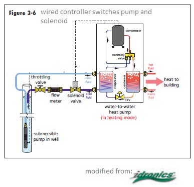
|
 Attachment: HXwSolenoid.png Attachment: HXwSolenoid.png
|
|
|
|
Blake Clark
New Member
Posts:55
|
| 27 Jun 2012 05:11 PM |
|
A semi-direct valve is a hybrid between direct acting and pilot acting. At low pressures - something like 5psi differential plus or minus - it actuates using the solenoid. So, yes, it can close completely without pressure. At higher pressure differentials its action is identical to a pilot operated valve, complete with slow action. It also has that pesky pilot port. My guess is that your pressure differential probably puts you in the "higher pressure" category, but you'd need to check the manufacturer's specs.
You'd need to explain what you have in mind for with the check valve, I'm not sure how that fits in. My guess is that you're looking at a pump-inlet application rather than a discharge to siphon application. The check valve there is to prevent water from running backwards when the "suction" turns off. Your problem is that the water is going want to keep running forwards into your negative pressure discharge line when the "pressure" turns off.
Remember, you're trying to hold as much pressure in the system as possible and your discharge line is trying to pull a vacuum. Once the pump shuts down, your discharge line is going to win the battle decisively in a matter of milliseconds. |
|
|
|
|
nooboo
Basic Member
Posts:136
|
| 27 Jun 2012 05:34 PM |
|
Posted By Blake Clark on 27 Jun 2012 05:11 PM
...At low pressures - something like 5psi differential plus or minus - it actuates using the solenoid.
Capiche?...Not Pressure actuated
...not controlled with pressure,
but when the wired controller says
..."No mora pumpa run"
(edit) power goes off to solenoid, closing it and
..."thata Closa that valva"
which will keep both in sync...
And the check valve is necessary, until I hear back otherwise from Dudadiesel, that this is a semi-direct, not direct actuated solenoid. A semi-direct would bleed past the solenoid, as I understand it.
Dudadiesel:
*Solenoid valves of 1" ports and smaller are only able to handle full vacuum. Larger valves are unable to operate near full vacuum.
also a vacum break should be in there. As jonr says
a vacuum break on the discharge. Keeping pressure high and temperature low will minimize fouling.
Perhaps a check valve is not what is needed, but the atmospheric vacuum breaker? |
|
|
|
|
| You are not authorized to post a reply. |
|
Active Forums 4.1
 |
Membership: |
 |
Latest:
croccohvacusa |
 |
New Today:
0 |
 |
New Yesterday:
0 |
 |
Overall:
35027 |
 |
People Online: |
 |
Visitors:
338 |
 |
Members:
0 |
 |
Total:
338 |
|
|
|