decafdrinker

Basic Member

Posts:420
 |
| 08 Aug 2010 06:53 AM |
|
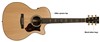
GeoMax 2, DSH, 4 ton, SE PA, Take a look at the picture. It's my system; I drew in the pipes as they are connected. The GeoMax (bottom), the "Water Out" goes to the Geo-Flo Circulators (middle), specifically the pump showing the "up" arrow in this picture, then to the RETURN side of the manifold and out to the loops. Could this be why the flow gauges aren't working correctly? Should this pipe have gone to the SUPPLY side with the gauges, then out to the loops?
 (Click the thumbnail above to open the full-sized picture, please let me know if I did it right....first time posting a pic) Then the fluid returns from the loops, into the manifold side labeled "SUPPLY" with the guages, goes down to the GeoFlo Circulator (down arrow), and back into the GeoMax "Water In".
|
|
|
|
|
|
|
engineer

Veteran Member
Posts:2749
|
| 08 Aug 2010 09:31 AM |
|
Possibly - the pic is so small I can't tell, but the flow guages may only properly indicate in one direction. |
|
Curt Kinder <br><br>
The truth is incontrovertible. Malice may attack it, ignorance may deride it, but in the end, there it is - Winston Churchill <br><br><a href="http://www.greenersolutionsair.com">www.greenersolutionsair.com</a>
|
|
|
decafdrinker
Basic Member
Posts:420
|
| 08 Aug 2010 09:32 AM |
|
I tried to make it a clickable thumbnail.... I've put the full-sized image on my personal website: http://www.wyss-leclair.com/geopic.jpgand tried to inline-it full sized below: The upper pipe of the manifold is labeled RETURN, and the lower pipe SUPPLY  |
|
|
|
|
Bergy
Basic Member
Posts:277
|
| 08 Aug 2010 11:04 AM |
|
They are reversed. Water should flow INTO the supply manifold and OUT of the return.
Bergy
|
|
|
|
|
rjdalga

New Member
Posts:32
|
| 08 Aug 2010 11:53 AM |
|
Yes, they are reversed as Bergy said. Take a look at the color coding on the manifold (blue and red). Water out should be going to the blue manifold and vise versa. |
|
| RJDalga, CRI<br>Home Analysts, Inc.<br>Kalamazoo, MI 49009 |
|
|
heatoftheearth
Basic Member
Posts:113
|
| 08 Aug 2010 11:56 AM |
|
Yup they're reversed. Should be an easy fix |
|
|
|
|
geotek
Basic Member
Posts:154
|
| 09 Aug 2010 06:10 PM |
|
I question the flow center arrows normally the right pump (facing flow center) is the water inlet from loop.
You can check this by pulling the bottom fitting from the right hand pump and insert your finger. If you feel the impeller it's pumping at you.
Loops have no direction but the freeze protection thermistor in the unit is usually oriented near the inlet water connection.
|
|
|
|
|
decafdrinker
Basic Member
Posts:420
|
| 09 Aug 2010 06:16 PM |
|
The arrows are definitely correct as noted. I highlighted them in black, but those are the directions. I guess it's possible the flow center, too, is upside down, but the pumps are on the lower position, but that shouldn't matter. My big concern is the the flow of water, while correct through the GeoMax air handler and Flow Center, is incorrect through the manifold, therefore making the gpm gauges not work correctly. They all read zero, no matter what. Not sure how the system loops were balanced without any indication of flow.
Thanks everyone for your input. I've also contacted Rehau and Heat Controller Inc and will be passing on the info to my installer. |
|
|
|
|
geotek
Basic Member
Posts:154
|
| 09 Aug 2010 07:21 PM |
|
The flow center is defiantly not upside-down as the valves are always on top.....but I have seen them marked wrong.
|
|
|
|
|
decafdrinker
Basic Member
Posts:420
|
| 09 Aug 2010 08:40 PM |
|
On my flow-center, the arrows are physically stamped into the metal...I just highlighted them in black for visibility. When I get a chance, I'll check the impellers. I/m pretty sure the problem is only with the manifold itself being backwards, which several people have said, "Yep, it is".
How to flow/gpm gauges actually work? Is there a little plunger-thing in there that is sucked/pushed by the water flowing? |
|
|
|
|
decafdrinker
Basic Member
Posts:420
|
| 09 Aug 2010 08:46 PM |
|
At this point, I'm more concerned about the almost constant knocking noise from the manifold during operation, the absurdity of trying to balance each loop without any indications of actual flow in each pipe, and the lack of any reply from my installer either by phone or email about those problems.
If anyone can recommend a good contractor in the SE PA area, especially one familiar with GeoMax (Heat Controller) and Rehau, I'd appreciate it. Hannabery has a great reputation, but they only service geo systems they've installed. |
|
|
|
|
ilgeo
Basic Member
Posts:180
|
| 11 Aug 2010 07:26 PM |
|
This is your ground loop manifold and you have what appears to be 4 loops that are a 300' long minus what is inside the house and the first 10' outside of the house that should be insulated. some concerns here 1st there is no need to balance if the loops are the same length. 2nd What type of tube is this It looks like 3/4" pex but is impossible to tell by picture. If it is then flow comes into question as does the amount of geo field piping. Appears to be an amateur job as pros dont use balancing manifols designed for radiant heat. Hdpe with fusion weld fittings are the norm. Romex cant be used for wiring equipment and pumps as there is no mechanical protection from damage...eric
|
|
|
|
|
joe.ami
Veteran Member
Posts:4377
|
| 11 Aug 2010 11:06 PM |
|
There is no need to "balance" loops if you have desired ewt and gpm.
The only thing you can do is restrict flow. That will seldom enhance performance.
I do not agree that all loops must be equal, nor am I saying it is undesireable. The real question (as always) is; are design temps achieved? It is less important how you get there.
joe |
|
Joe Hardin
www.amicontracting.com
We Dig Comfort!
www.doityourselfgeothermal.com
Dig Your Own Comfort! |
|
|
decafdrinker
Basic Member
Posts:420
|
| 11 Aug 2010 11:14 PM |
|
Hmmm...ok...some further thoughts :-)
I know it doesn't show in the picture, but I know that the adjustable valves that control flow in each loop are all not set at the same level....so at some point, my installer did adjust them, but I'm not sure to what.
In regards to design temp, I have so much paperwork, and much was not explained to me. I know that for the summer, the system is doing an AWESOME job at a/c...assuming the bills I'm getting (see a different thread) are reasonable...I honestly don't know if the system could be more efficient.
I know this past winter in PA, where it was much colder than usual, the system had a lot of trouble keeping up with the cold. The aux heat was on quite a bit. Some people attributed this to the system being sized for cooling, others to the ground loops being "freshly dug" and needing time to settle. I have no idea which is correct, and I think another winter might help determine the system performance. I understand that the system is probably sized for cooling and probably undersized for heating...I just wonder if the loop performance could have been better. I was unable to take P/T readings at the time.
er...the electrical connections should be that armored cable, right? and not the plain ROMEX? because it's a place where it could be damaged? The system passed inspections by the township here, though. |
|
|
|
|
decafdrinker
Basic Member
Posts:420
|
| 11 Aug 2010 11:16 PM |
|
I believe it's 1" pex, but I'll check on that. I don't think the first 10 feet OUTSIDE the house are insulated. No mention of that was made. The PEX runs about 20 feet horizontally after leaving the basement underground, and then down the bore holes. So should 30 feet be insulated?? |
|
|
|
|
joe.ami
Veteran Member
Posts:4377
|
| 11 Aug 2010 11:18 PM |
|
When you say "aux was on quite a bit" do you know design balance point?
j |
|
Joe Hardin
www.amicontracting.com
We Dig Comfort!
www.doityourselfgeothermal.com
Dig Your Own Comfort! |
|
|
decafdrinker
Basic Member
Posts:420
|
| 11 Aug 2010 11:26 PM |
|
Would it be in the paperwork from the installer? |
|
|
|
|
joe.ami
Veteran Member
Posts:4377
|
| 11 Aug 2010 11:41 PM |
|
Hopefully. If you have a bin report it will show what temperature aux begins to engage.
j |
|
Joe Hardin
www.amicontracting.com
We Dig Comfort!
www.doityourselfgeothermal.com
Dig Your Own Comfort! |
|
|
geome

Advanced Member
Posts:987
|
| 12 Aug 2010 08:05 AM |
|
Posted By stuart.wyss on 11 Aug 2010 11:14 PM
I know this past winter in PA, where it was much colder than usual, the system had a lot of trouble keeping up with the cold. The aux heat was on quite a bit. I'm not saying your unit was sized correctly, or not. But, I believe, the passage above would be consistent with a harsh winter and standard geothermal sizing practice since 20 year temperature averages are used. That is, in a heat dominated climate, outdoor temperatures below the winter average would make aux heat come on more, and outdoor temperatures above the winter average would make aux heat come on less. Your first winter with your geothermal system was a brutal one and hopefully won't be typical. Our report from a different manufacturer lists outdoor temperatures along the left side of the report, and anticipated system running hours and aux heat hours in different columns (on the same page). I believe the point at which we see the first aux heat coming on is at 17f, for us. Look for a page that shows something like this, or that indicates "design temperature" or perhaps "balance point" (someone please correct me if this terminology is not accurate.) |
|
| Homeowner with WF Envision NDV038 (packaged) & NDZ026 (split), one 3000' 4 pipe closed horizontal ground loop, Prestige thermostats, desuperheaters, 85 gal. Marathon. |
|
|
ilgeo
Basic Member
Posts:180
|
| 12 Aug 2010 10:55 AM |
|
stuart, The od of pex is based on cts sizes which are 1/8 over so 3/4 is 7/8od and 1" is 1 1/8od. I thought you had a horizontal trench which is why I questioned the amount of tubing.
flexible metal conduit and emt should be used where wiring is exposed within 7' of the floor NEC article 334.15 |
|
|
|
|