ICFconstruction

Veteran Member

Posts:1324

 |
| 03 Jan 2016 11:35 AM |
|
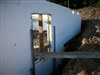
This lintel design (attached) was on a plan for over a 16'garage door opening. I haven't seen one like this before. It is like they are treating it as two 12" lintels instead of one 24".
Any thoughts? |
 Attachment: 24_Lintel.png Attachment: 24_Lintel.png
|
| Brad Kvanbek - ICFconstruction.net |
|
|
|
|
jameserizer

New Member
Posts:19
|
| 03 Jan 2016 12:21 PM |
|
Don't see your attachment but maybe that's just me. Going in blind, I am guessing that you have two 12" tall beams, one atop the other? If so, maybe the problem is no shear connection between the two beams, so any bending forces develop across the 12" height (x2) instead of across the 24" height?
Think about a sheet of plywood. How strong and stiff would that plywood be in bending if it was just a stack of loose plys with no glue? Pretty floppy. Add glue and bond the plys together and it becomes dramatically stiffer. Same deal with beams stacked vertically and no shear connection (glue) between them.
|
|
|
|
|
ICFconstruction
Veteran Member
Posts:1324
|
| 03 Jan 2016 12:30 PM |
|
Sorry, I think the attachment is there now. |
|
| Brad Kvanbek - ICFconstruction.net |
|
|
jameserizer
New Member
Posts:19
|
| 03 Jan 2016 12:44 PM |
|
OK, I see it now. Hmmm....that looks pretty wacky. I'm an M.E., not a C.E. but I can't see any reason to do it like that. Why break the stirrups? Why no cross ties, especially at top and bottom of the cage? Also, why the #6 bar? That seems heavy gauge. I would definitely ping the structural engineering firm about this one. Those guys don't always do a good job, you know. They really screwed up my house and I made them completely re-do the whole thing. Most of the column, beam, lintel, and roof beam details changed as a result. I almost had to go for a completely new plans review with the county but we managed to fake them out by claiming 'clarifying remarks'. |
|
|
|
|
newbostonconst

Advanced Member
Posts:778
|
| 03 Jan 2016 01:13 PM |
|
That design does not look like standard code design.
Is the roof sitting on that wall? Load bearing.
What is the span of the roof?
Lintel height is 24 inches?
Wall thickness is 6 inches?
With that info it is easy to look in the code book and figure out what you need.
http://publicecodes.cyberregs.com/icod/irc/2012/icod_irc_2012_6_sec011.htm |
|
| "Never argue with an idiot. They will only bring you down to their level and beat you with experience." George Carlins |
|
|
jameserizer
New Member
Posts:19
|
| 03 Jan 2016 01:57 PM |
|
I think you might be over-simplifying things a bit, New Boston. The UBC does not do your engineering for you, it merely gives guidelines and requirements for structural engineers to meet. |
|
|
|
|
ronmar

Basic Member
Posts:479
|
| 03 Jan 2016 02:10 PM |
|
Is it between two planned pours? IE: It might be that the lintel wound up across the cold joint between upper and lower wall? I spent a lot of time in the PCA100 prescriptive tables this past year and am pretty sure a 16' span needs more than a 12" lintel in a non load bearing wall(probably more in a load bearing). If that lintel wound up between planned pours, a set of stacked bond beams might be a solution to maintain the same build/pour plan. What siesmic zone is this in? The number 6's might mean this is for a load bearing wall. It could also have been deemed necessary to tie into a diaphram for out of plane forces... |
|
|
|
|
ICFconstruction
Veteran Member
Posts:1324
|
| 03 Jan 2016 03:07 PM |
|
A second story is above it. I would probably stop a pour about 3' above the door. It is some big bar in the 6" ICF and does not look like anything I have seen before. Thought maybe the engineer didn't think stirrups could go from one course to the next. |
|
| Brad Kvanbek - ICFconstruction.net |
|
|
smartwall
Veteran Member
Posts:1209
|
| 03 Jan 2016 06:42 PM |
|
It looks like because of the notations, that the engineer wants to make sure there is enough mud around the rebar. The stirrup design looks like he wants to maintain separation between the rebar top and bottom on both sets. Interesting |
|
|
|
|
smartwall
Veteran Member
Posts:1209
|
| 03 Jan 2016 06:42 PM |
|
If it's stamped, go with it |
|
|
|
|
jameserizer
New Member
Posts:19
|
| 03 Jan 2016 07:04 PM |
|
I don't know if I'd run with that advice, Smartwall. I am an engineer and I can tell you, engineers do stupid things sometimes. Doh! If you are building this house for a customer and you just don't care, run with whatever is stamped. If you are building it for yourself and/or you give a hoot about how well it turns out or possibly to avoid a potential future lawsuit and you see something squirrely like this on the plans, question it! Call the engineer and ask him: "WTF, dude??". He/she will say "Here's why I want it done that way" or "You know, since you brought it up, I can think of a better way to do it" (nice save, eh?) or "Oops, let me get back to you on that". Either way you can feel better about what you are building.
The beam would be a lot stronger if the stirrups ran the whole height of the cage and f they bridged across the bottom. Four separate stirrups don't do much for resisting shear. This could well be a mistake or there could be something else going on that drove this design decision but Brad is right to question this, IMO.
Edit: I think the stirrups would be best to bridge across the top, too...or maybe alternate deep C stirrups, one left, and one right. What is the horizontal spacing requirement, Brad? Where there is a lot of shear they usually want 8" CTC or thereabouts.
|
|
|
|
|
ICFconstruction
Veteran Member
Posts:1324
|
| 03 Jan 2016 07:19 PM |
|
So it is not just me. I thought maybe I was missing something. I will inquire, but I knew I would hear quicker here than calling the engineer. |
|
| Brad Kvanbek - ICFconstruction.net |
|
|
dmaceld
Veteran Member
Posts:1465

|
| 03 Jan 2016 07:45 PM |
|
Keep this in mind. A beam with uniform top loading (even point loads) will have the top half in compression and the bottom half in tension. The centerline is not in compression nor tension. That's why you drill holes for pipes, wires, etc., in the middle of floor joists. In a design for a lintel rebar in the center of the beam and above is of no value in the strength of the beam. All it does is help hold the concrete together. Since concrete has no tensile strength all of the strength of a concrete beam below center is in the rebar, hence the importance of its adhering to the concrete. The stirrups only help hold everything together in place until the concrete sets. In a 16' beam it makes sense to have the large rebar but I think more smaller rebar is better as you have more adherence of concrete to steel.
I would seriously question the validity of the design shown here. OK, I just looked at the figure again. It looks like the idea is two separate 12" beams, one on top of the other. That is nowhere near as good as a single 24" beam, IMO. The bending moment of a beam is proportional to the cube of its depth. In steel or wood where the material has both compressive and tensile strength a 24" beam will be 8 times as strong as a12" beam. Stacking two 12" beams simply doubles the overall strength so the 24" will be 4 times stronger than two 12". I'm not real familiar with concrete design so I'm sure this analogy is not 100% applicable, but I'll go out on a limb and say it is pertinent.
The "C" design of the subject stirrups won't assure that the longitudinal rebar won't fall loose during concrete placement unless they're wire tied together. PP design in my book.
|
|
| Even a retired engineer can build a house successfully w/ GBT help! |
|
|
Baldwin2014
New Member
Posts:24
|
| 04 Jan 2016 12:08 PM |
|
The most likely scenario behind this "doubled-up" design is that you have post and beam ICF forms. However this makes no sense as post and beam forms cannot give the clearance that the detail shows.
Suggest you do the following - contact your ICF tech support and have them call your EOR. It's that easy... |
|
|
|
|
ICFconstruction
Veteran Member
Posts:1324
|
| 04 Jan 2016 05:59 PM |
|
Posted By Baldwin2014 on 04 Jan 2016 12:08 PM
The most likely scenario behind this "doubled-up" design is that you have post and beam ICF forms. However this makes no sense as post and beam forms cannot give the clearance that the detail shows.
Suggest you do the following - contact your ICF tech support and have them call your EOR. It's that easy...
I distribute ICFs, so I guess I am tech support. I can inquire to the engineer. But it is more fun to ask here. |
|
| Brad Kvanbek - ICFconstruction.net |
|
|
jonr

Senior Member
Posts:5341
|
| 05 Jan 2016 06:58 PM |
|
Stacking two 12" beams simply doubles the overall strength so the 24" will be 4 times stronger than two 12". I think it is "stiffer", which isn't the same thing. My guess is that a rectangular 6"x24" reinforced concrete beam is too high of a height/width ratio for the rebar spec being used. |
|
|
|
|
dmaceld
Veteran Member
Posts:1465
|
| 06 Jan 2016 12:55 AM |
|
Posted By jonr on 05 Jan 2016 06:58 PM
Stacking two 12" beams simply doubles the overall strength so the 24" will be 4 times stronger than two 12".
I think it is "stiffer", which isn't the same thing.
Well, yeah, I suppose that might be, but a beam's resistance to bending is part of the science of strength of materials! On the other hand, wouldn't you say a 2" diameter rope is 4 times stronger than a 1" rope as it will hold up 4 times as much weight? If it takes 4000 lbs to bend 24" deep beam 1" and 1000 lbs to bend a double 12" beam one inch, then isn't the 24" one 4 times as strong? Interesting game of semantics and differences in definitions, really. |
|
| Even a retired engineer can build a house successfully w/ GBT help! |
|
|
jameserizer
New Member
Posts:19
|
| 06 Jan 2016 11:49 AM |
|
You are comparing the beams section modulus, which is primarily geometrical, with its material properties. Where this breaks down, literally, is at the compressive strength limit of the concrete and the actual construction of the concrete beam, which is a complex composite structure. No one can say, off-the-cuff, that a reinforced concrete beam with twice the height of a similar beam would be N times stronger or stiffer without actually calculating the beam, due to it's complex construction. You could do that with a metal bar because it is isotropic and simple, but with concrete, it is the design and size of the rebar cage and compressive strength that dominates. Steel beams are easy to figure...reinforced concrete is harder. That was a poor choice of words; I should say 'more difficult' :-) |
|
|
|
|
Baldwin2014
New Member
Posts:24
|
| 07 Jan 2016 01:14 PM |
|
Posted By ICFconstruction on 04 Jan 2016 05:59 PM
Posted By Baldwin2014 on 04 Jan 2016 12:08 PM
The most likely scenario behind this "doubled-up" design is that you have post and beam ICF forms. However this makes no sense as post and beam forms cannot give the clearance that the detail shows.
Suggest you do the following - contact your ICF tech support and have them call your EOR. It's that easy...
I distribute ICFs, so I guess I am tech support. I can inquire to the engineer. But it is more fun to ask here.
I mean you should contact the ICF manufacturer's technical rep - they have to have someone with structural knowledge that can help. Its one thing to approach your engineer and tell him/her you don't like their detail because you/GBT don't like it.... Approach them with the ICF manufacturers structural guy and you will see changes right away... Someone said earlier that engineers make mistakes - oh so true they are not superhuman - just my $0.02. |
|
|
|
|
newbostonconst
Advanced Member
Posts:778
|
| 07 Jan 2016 08:05 PM |
|
In my experiance ICF manufactures don't have "structural guys". They are plants that make things out of foam.....they are "foam guys" They make lots of cups and containers. |
|
| "Never argue with an idiot. They will only bring you down to their level and beat you with experience." George Carlins |
|
|